13/05/2017 -
WEC 2017 season is moving forward after prologue at Monza, first race at Silverstone and last race at Spa Francorchamps.
Monza as a circuit was a good opportunity to test new cars on low downforce configuration measuring performance on long straight with significant top speed.
Silverstone need a different aero setting, certainly with higher level of downforce on its several high lateral g corners.
Finally Spa, again a good training session considering Le Mans.
LMP1 are very complex and sophisticated race cars that over the season offers plenty of opportunities to small development kit, generally known as micro aerodynamics refinements.
Speculation on blown diffuser have been very intense on recent period. Toyota seems to be a step forward on using this trick to clean side pod flow and improve efficiency of rear diffuser.
Drawing below clearly shows the intake over the floor, used to divert airflow over the rear diffuser surface.
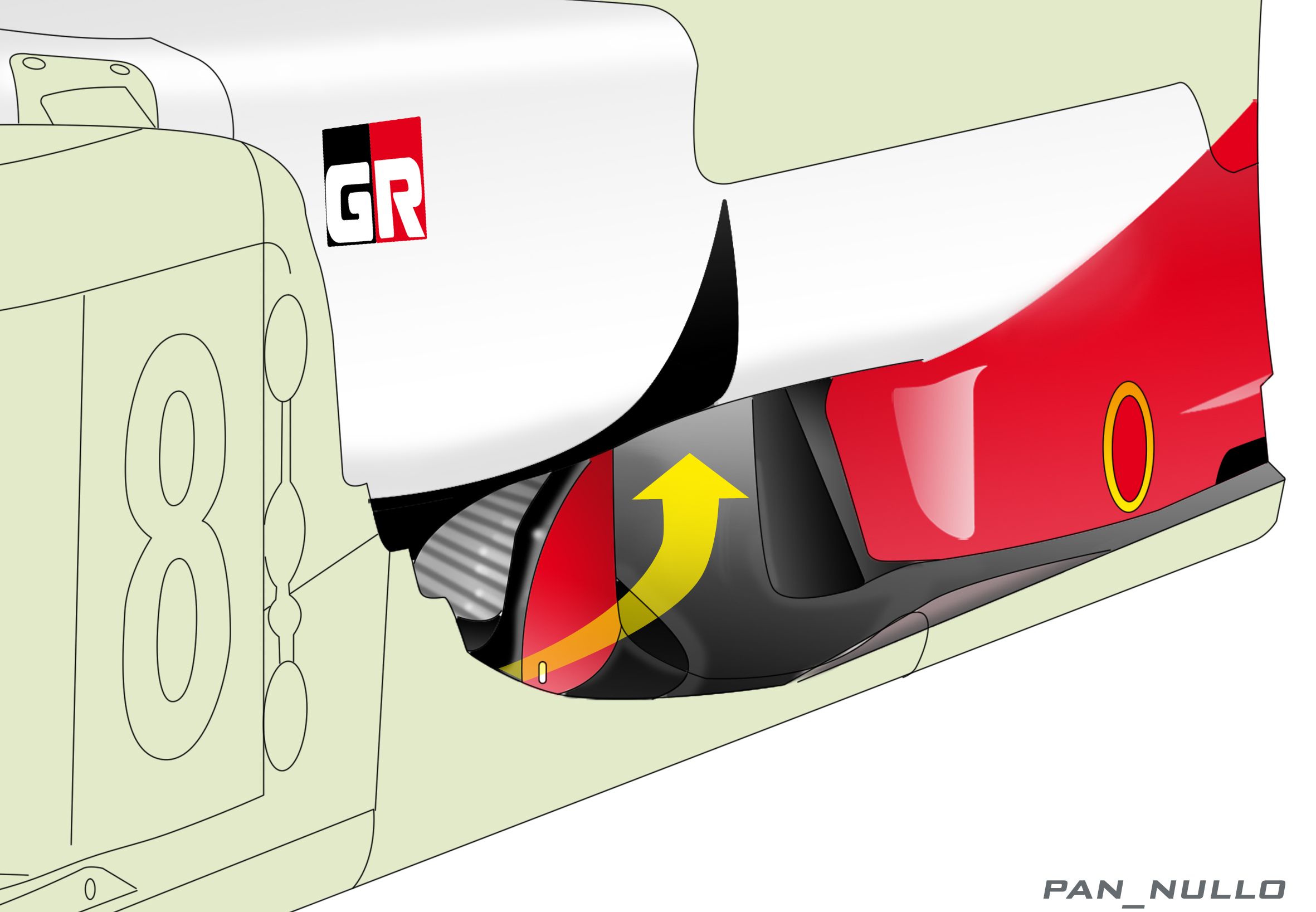
Toyota TS50 - details of side pod intake
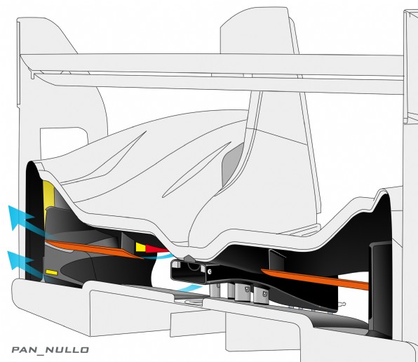
Inside tunnel with unconventional location of intercooler. Exchanger is raised significantly from the floor in order to allocate proper section to the intake that feed the top of rear diffuser.
Considering the great deal of attention on positioning internal components with minimum impact on vertical centre of gravity, there should be a good positive gain on adopting such a design….

Toyota TS50 – Tunnel intake, rised intercooler installation and air duct to rear diffuser
Good example of micro aero development. New fence design on rear fender, to better control flow direction over inside convex surface. Fence location seems unchanged showing a more efficient fixation method on vertical surface. Single curved element rather that 3 mounting towers and additional flow guide with horizontal plate.

Toyota TS50- New rear fender exit details – Left Monza, Right Spa
Drum on rear hub shows a turning vanes on lower side. Does it push addition flow on rear diffuser ? Or is intended to control vortex on very complex area inside rotating wheel ?
Very difficult to answer without doing specific analysis. Certainly this proves the high level of aero refinement.

Toyota TS50 - Turning vanes on rear hub drums
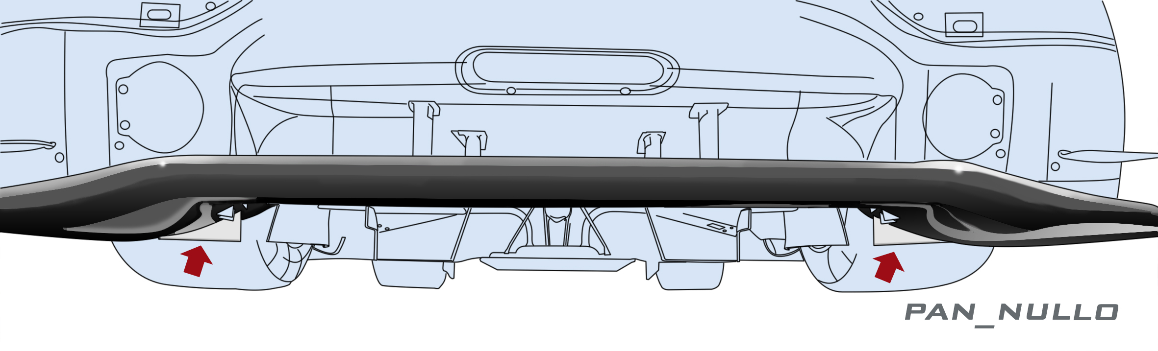
Extensive use of VG’s on suction side of front splitter. VG design seems conventional, but positioned very closed to splitter main leading edge. Flap element is very curved therefore VG’s ensure proper level of vorticity to avoid separation. As expected centre part of splitter with less local downforce works with VG closed to trailing edge.

Toyota TS50 - VG’s on suction side of splitter main section
Strakes and VG’s on side part of front fender. Position and design of these appendices creates local flow separation and vortex that seals centre part of the slitter, responsible to create downforce, and interfere with complex flow inside rotating front wheels.
Porsche 919 Hybrid - details of VG’s ahead of front tyres
New front fender shape on Kolles. Clear flow channel recessed ahead of wheel arc cut-outs. More squared lateral profile. Tendency is to control local flow on top on mandatory cut-outs.

ByKolles – updated front fender